
How Does IPTV Work? Technology Explained Simply
IPTV (Internet Protocol Television) works by distributing television programming as digital data packets over standard Internet Protocol (IP) networks using a packet-switched, pull-based delivery model. Unlike traditional cable or satellite systems that continuously broadcast all channels simultaneously over radio frequency (RF) signals, an IPTV network only transmits the specific stream requested by the client device.
The delivery pipeline operates in four major phases:
- Acquisition & Encoding: Raw feeds are ingested from satellites or fiber links and compressed using video codecs like H.264, H.265 (HEVC), or AV1.
- Packaging: Compressed video and audio streams are encapsulated into containers—MPEG-TS for live broadcasts or fragmented MP4 (fMP4) for on-demand media—alongside dynamic manifest index files (M3U8 for HLS or MPD for DASH).
- Distribution: Streams are cached on regional Content Delivery Network (CDN) edge nodes. Live TV is routed across private ISP networks via IP Multicast using IGMPv3 protocols to conserve bandwidth, while Video-on-Demand (VOD) uses IP Unicast connections.
- Playback: The client player parses the manifest, employs Adaptive Bitrate (ABR) heuristics to dynamically switch resolutions based on bandwidth fluctuations, and utilizes the device’s hardware SoC to decode and display the video.
What Is IPTV and How Does It Work?
Internet Protocol Television (IPTV) is the delivery of television content over IP-based networks rather than traditional terrestrial, satellite, or cable formats. Traditional cable TV broadcasts the entire frequency spectrum down physical lines, forcing the receiver to filter a single channel. In contrast, IPTV is a pull-based media system where the network routes only the specific stream requested by the client device. This selective delivery model optimizes network bandwidth and supports interactive services like timeshifted television and network-based recording. Modern architectures utilize a hybrid model: live feeds are broadcast via IP Multicast to conserve backbone bandwidth, while Video-on-Demand (VoD) and catch-up services are delivered via IP Unicast to individual subscribers. For more context on adoption trends, see what is IPTV.
IPTV vs. OTT vs. Cable/Satellite Comparison
To understand why IPTV is structurally different from standard streaming services and traditional television, review the primary architectural differences:
| Feature | IPTV (Managed Network) | OTT (Public Internet) | Cable/Satellite (RF Coaxial/Dish) |
|---|---|---|---|
| Delivery Medium | Private, operator-managed IP network (VLAN-isolated) | Public internet (best-effort delivery) | Dedicated radio frequency (RF) spectrum |
| End-to-End Latency | Very low (1–3 seconds via UDP multicast) | Moderate-to-high (6–18 seconds via HTTP unicast) | Lowest (sub-second broadcast delay) |
| Quality of Service (QoS) | Yes (enforced by network priority queues) | No (vulnerable to network congestion) | Physical isolation prevents interference |
| Bandwidth Impact | Zero impact on general internet traffic (multicast) | Competes with other local network downloads | Direct transmission; burns zero LAN bandwidth |
| Primary Use Cases | Live telco television services (Bell Fibe, Telus Optik) | Web-based video apps (Netflix, YouTube, RiverTV) | Standard residential cable bundles and dish receivers |
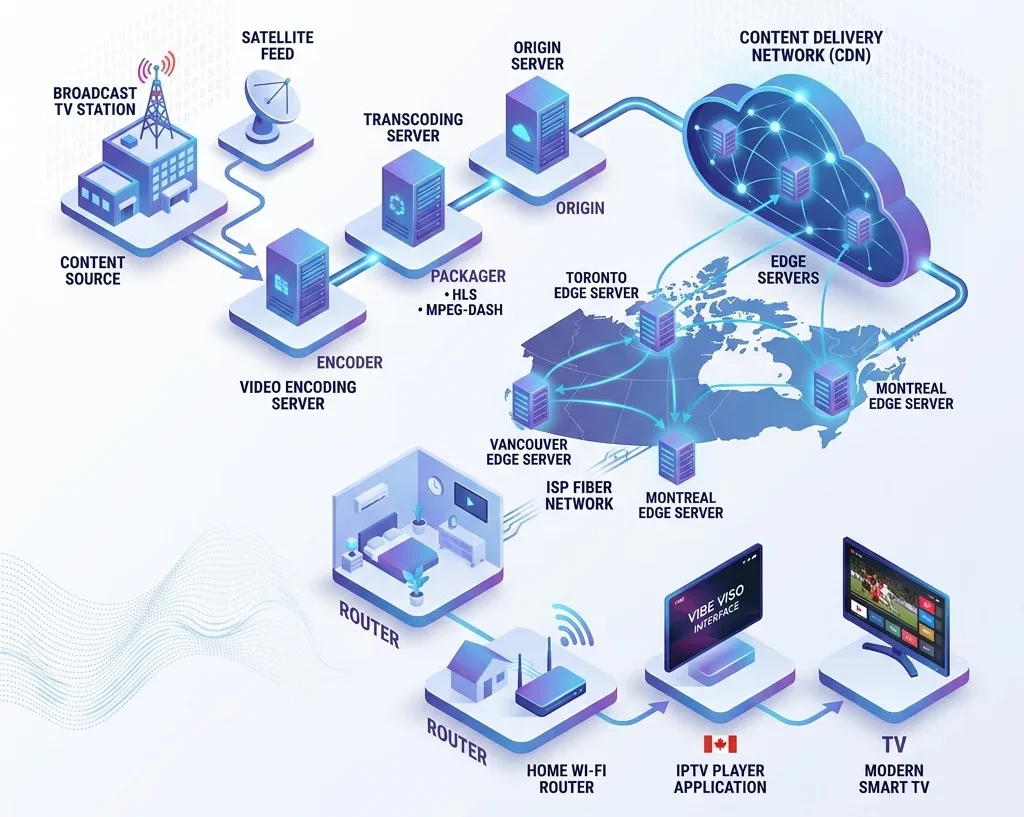
The end-to-end IPTV pipeline follows this path:

Each stage of the pipeline plays a specific role in maintaining stream flow:
- Content Source: Ingestion point for raw signals from direct fiber links, satellite downlinks, terrestrial broadcasts, or cameras.
- Encoder: Compresses raw baseband video into digital formats using H.264 (AVC) or H.265 (HEVC) codecs.
- Transcoder: Converts the encoded stream into multiple resolution and bitrate profiles, creating an Adaptive Bitrate (ABR) ladder to handle variable connection speeds.
- Packager: Encapsulates transcoded streams into delivery containers (like HLS
.m3u8or DASH.mpdsegments, or MPEG-TS for multicast). - Origin Server: The central repository hosting packaged media chunks and manifests, serving as the source for CDN pulls.
- CDN Edge: Distributed caching servers colocated at regional ISP Points of Presence (POPs) that intercept viewer requests locally to reduce latency. To learn which services utilize Canadian POPs, see best IPTV services across Canada.
- ISP Network: Transit infrastructure routing IP packets over fiber backbones, using DSCP tags for video packet prioritization.
- Home Router: Customer-premises gateway routing packets to decoders and using IGMP snooping to prevent local network flooding.
- IPTV Player: Client software parsing manifests, fetching chunks, managing a jitter buffer, and handling DRM. For client setup guides, consult the IPTV setup guide or see how to install IPTV on Firestick in Canada.
- TV Display: Physical screen rendering decoded progressive frames via HDMI and playing synchronized audio. For cost comparisons, see IPTV pricing in Canada.
How live TV reaches your screen: A step-by-step walkthrough
To trace this pipeline, consider a live TSN sports broadcast of a soccer match. At the stadium, a 4K camera captures video at 60fps, sending uncompressed 12 Gbps baseband video via 12G-SDI to an Outside Broadcast (OB) van. The production team mixes the feed and encodes it into a 50 Mbps HEVC contribution stream, transiting it via Secure Reliable Transport (SRT) over fiber to the broadcast center.
At the center, transcoders convert the feed into an ABR ladder (e.g., 1080p at 8 Mbps down to 480p at 1.5 Mbps). The packager segments the video into 2-second fragmented MP4 (fMP4) chunks, encrypts them via AES-128, and updates the HLS .m3u8 manifest. The origin server hosts these files, which are cached by local CDN edge nodes.
When a viewer selects the channel, the IPTV player retrieves the .m3u8 manifest from the local CDN. Selecting the 1080p stream, the player pulls sequential segments over the ISP’s GPON fiber network. GPON technology delivers up to 2.4 Gbps downstream using Wavelength Division Multiplexing (WDM) to multiplex multiple customer ONT connections. The packets flow to the home router, and then over Ethernet to the Set-Top Box. The player deposits chunks into a 3-second jitter buffer, negotiates DRM licenses, decodes the HEVC stream using the SoC’s hardware decoder, and displays the video on the TV screen via HDMI.
How IPTV Content Is Acquired: Ingest and Contribution
IPTV content acquisition, also known as ingest or contribution, is the process of collecting source television feeds from satellites, terrestrial antennas, local hardware interfaces, and live IP links, and routing them into the IPTV headend for processing. The reliability and fidelity of the IPTV service are bounded by this acquisition layer.
Satellite feeds (DVB-S/S2)
Satellite downlinks remain a primary source for linear ingest. Raw C-band (3.7–4.2 GHz) or Ku-band (11.7–12.7 GHz) signals are received by geostationary satellite dishes. At the dish’s focal point, a Low-Noise Block downconverter (LNB) amplifies the weak microwave signal and downconverts it to the L-band (950–2150 MHz) to minimize attenuation in coaxial runs to indoor receivers. Channels are multiplexed onto specific transponders using horizontal or vertical polarization. The indoor Integrated Receiver/Decoder (IRD) demodulates the signal using QPSK, 8PSK, or 16APSK (DVB-S/S2 standards), applies forward error correction (FEC) like LDPC and BCH codes, and extracts the raw multi-program transport stream (MPTS).
Terrestrial TV broadcast (ATSC 1.0/3.0)
For local channels, operators ingest over-the-air (OTA) RF signals using high-gain directional Yagi-Uda or panel antenna arrays. A digital tuner demodulates these signals. ATSC 1.0 utilizes 8-VSB (8-level Vestigial Sideband) modulation to carry a single MPEG-2 stream up to 19.39 Mbps per 6 MHz channel. The modern ATSC 3.0 (NextGen TV) standard utilizes Coded Orthogonal Frequency Division Multiplexing (COFDM) modulation. ATSC 3.0 transmits media via IP-based protocols (Route or MMT) rather than MPEG-TS, and supports HEVC compression, Dolby AC-4 audio, and Physical Layer Pipes (PLPs) to deliver 4K HDR and mobile-resilient feeds.
SDI/HDMI hardware ingestion
For uncompressed baseband video ingestion within studios, operators use physical capture hardware. The industry standard is the Serial Digital Interface (SDI), transiting uncompressed digital video over 75-ohm coaxial cables with BNC connectors. Bandwidths range from HD-SDI (1.485 Gbps) up to 12G-SDI (11.88 Gbps) for 4K video. Transcoder servers utilize high-bandwidth PCIe capture cards (e.g., Blackmagic DeckLink or AJA KONA) which act as DMA (Direct Memory Access) bridges. These cards write raw YUV frames directly into system RAM with zero CPU overhead, enabling real-time software transcoding. HDMI ingest is used for prosumer feeds, requiring HDCP key negotiation.
Live production feeds
Live sporting events and remote broadcasts utilize Outside Broadcast (OB) vans acting as mobile control rooms. Switchers mix camera feeds and export the program output. For remote production (REMI), camera feeds are encoded at the venue and sent over IP. Modern IP-based studios utilize the SMPTE ST 2110 suite of standards over 100GbE fiber. ST 2110 splits video (ST 2110-20), audio (ST 2110-30), and metadata (ST 2110-40) into independent multicast streams. Synchronization is maintained using Precision Time Protocol (PTP – IEEE 1588) to ensure sub-microsecond alignment of separate streams across the network.
IP contribution protocols
When routing live feeds over long distances, operators use robust IP contribution protocols over UDP rather than TCP. Secure Reliable Transport (SRT) utilizes an optimized Automatic Repeat reQuest (ARQ) error correction mechanism to dynamically retransmit lost packets without the high overhead of TCP. SRT features latency negotiation, packet jitter recovery, and AES encryption. Zixi is an enterprise alternative using advanced Forward Error Correction (FEC) and ARQ, supporting link bonding to combine multiple cellular and fiber connections. RTMP is a legacy TCP-based protocol; it is prone to head-of-line blocking, where a single lost packet stalls subsequent delivery, making RTMP less suitable for high-bitrate contribution than SRT.
The Four Architecture Layers of an IPTV Network
A functional IPTV network consists of four primary layers: the headend for content ingestion, the Content Delivery Network (CDN) for caching, the middleware for subscriber authorization, and the client device for decoding.
Each layer has a discrete job. Failure or misconfiguration at any one of them produces the symptoms users blame on “bad IPTV” — buffering, authentication errors, EPG gaps, or audio sync drift. Understanding each layer lets you diagnose problems precisely instead of guessing.
The headend — where TV content enters the IP world
The headend is the ingestion point where raw broadcast signals are converted into IP-deliverable streams. Signal acquisition happens via two primary paths: satellite downlinks using DVB-S or DVB-S2 receivers, and fiber-delivered SDI (Serial Digital Interface) feeds from broadcasters directly.
Once acquired, the raw signal hits the transcoding stack. Legacy channels encode to H.264/AVC — computationally cheap, universally supported. 4K and HDR content encodes to H.265/HEVC, which achieves roughly 50% better compression at equivalent quality. That efficiency is not optional at 4K; without HEVC, you’re pushing 50–80 Mbps per stream rather than 20–25 Mbps.
Audio tracks encode to AAC for standard stereo or Dolby Digital Plus (AC-3) for surround sound. Both ride inside the same MPEG-TS or fMP4 container as the video.
Encryption happens at this stage. The two dominant approaches are AES-128 (used in HLS-based delivery) and DVB-CSA scrambling (legacy DVB ecosystems). On top of transport-layer encryption, content protection layers through DRM systems:
- Widevine — Google’s DRM, used across Android and Chrome
- PlayReady — Microsoft’s DRM, used on Windows and Xbox
- FairPlay — Apple’s DRM, enforced on iOS, tvOS, and Safari
A stream that exits the headend is encrypted, compressed, segmented, and ready to traverse the CDN.
The CDN — caching content close to Canadians
The CDN sits between the headend’s origin server and the end user’s device. Its job is to eliminate the need for every stream request to travel all the way back to the origin.
Origin servers hold the master copies of streams. CDN edge nodes — colocated at ISP Points of Presence (POPs) — cache those streams regionally. For Canadian users, this means edge nodes in Toronto, Vancouver, and Calgary intercept stream requests locally rather than bouncing them to servers in the US or Europe.
The arithmetic here is straightforward. A Toronto viewer requesting a live NHL stream from an origin server in Dallas adds ~30–50 ms of round-trip latency and saturates expensive cross-border backbone links. The same viewer hitting a CDN edge node in a Toronto ISP datacenter sees sub-5 ms delivery latency and zero backbone cost per request.
Edge caching also handles traffic spikes. A live event with 50,000 concurrent viewers doesn’t generate 50,000 simultaneous pulls to the origin. The edge node fetches the stream once and fans it out locally. Backbone congestion drops. Quality holds.
For Canadians evaluating which providers actually have Canadian edge infrastructure, the guide to the best IPTV services across Canada maps out which services operate regional POPs versus relying solely on US-based CDNs.
The middleware — the brain behind your subscription
Middleware is the control plane of the IPTV system. It handles everything that isn’t the video stream itself.
The core function is AAA: Authentication (who are you?), Authorization (what are you allowed to watch?), and Accounting (how long did you watch it, for billing or concurrency enforcement?). Every time you open your IPTV app and the channel list loads, a middleware API call has already verified your credentials and returned a token.
EPG (Electronic Programme Guide) data flows through middleware via XMLTV feeds — structured XML files that carry channel metadata, schedule times, show descriptions, and series-link identifiers. The quality of the EPG you see is entirely a function of how well the provider’s middleware ingests and refreshes those feeds.
Middleware also manages the DRM key licensing server. When your device requests a protected stream, it contacts the middleware’s key server to obtain a decryption license. The key server validates your subscription status in real time before issuing the license. If your account is suspended mid-stream, the next key rotation fails and playback stops — no manual intervention required.
Catch-up TV and cloud-PVR run through middleware session management. The middleware tracks what you recorded, enforces recording windows (typically 7–30 days of lookback), and provisions time-shifted stream URLs that map to archived segments on the CDN or origin.
The client device — where your TV finally gets the signal
The client device reassembles IP packets into a watchable video signal. Two categories exist: hardware STBs and software players.
Hardware set-top boxes run SoC-based hardware decoders — application processors (typically ARM Cortex-A series) paired with dedicated video decoding silicon. The OS is either Android TV (common in consumer-grade boxes like Nvidia Shield, Xiaomi Mi Box) or a Linux RTOS (used in operator-provisioned STBs where the provider controls the full stack). Hardware decoding matters for 4K HEVC: software-decoding a 25 Mbps HEVC stream burns CPU cycles and introduces latency; hardware decoding offloads it entirely.
Software players run on existing Android, iOS, Windows, or smart TV hardware. The most capable options in the IPTV ecosystem:
- TiviMate — Android-only, the benchmark for EPG accuracy and multi-playlist management
- IPTV Smarters Pro — cross-platform, supports Xtream Codes and M3U natively
- GSE Smart IPTV — strong multi-device support with external player integration
To put any of this hardware or software to use, learn the setup steps for getting a client device configured end-to-end.
Expert Tip: Wire your STB or streaming device directly via Ethernet. Wi-Fi introduces jitter — microsecond timing variations in packet arrival — that accumulates into buffering and audio drift. A reliable IPTV stream requires sustained packet loss below the 10⁻⁶ threshold (one lost packet per million). Ethernet on a gigabit switch hits that reliably. Most home Wi-Fi environments do not.
The Mechanics of Video Encoding: Compressing Raw Broadcasts
Video encoding is the process of compressing raw, uncompressed broadcast feeds into digital formats suitable for efficient network transmission without sacrificing visual quality. A raw, uncompressed high-definition (HD) video feed at 1080p and 60 frames per second contains approximately 3 Gbps of data, which exceeds typical consumer bandwidth. To make this streamable, encoders exploit visual redundancies within and between frames to reduce transmission size by several hundred fold.
Spatial redundancy, or intra-frame compression, reduces data size within a single frame. Since neighboring pixels are often highly correlated (e.g., a solid blue sky), the encoder predicts pixel values using adjacent blocks. It then stores only the difference—the residual error—between the prediction and the actual frame, avoiding the need to record absolute pixel values repeatedly.
Temporal redundancy, or inter-frame compression, exploits similarities between consecutive frames in a video sequence. Because video displays at high frame rates, successive frames are highly similar. Temporal compression uses motion estimation to track moving blocks across frames. Instead of re-transmitting moving elements, the encoder calculates motion vectors that describe their displacement relative to reference keyframes (I-frames), generating predictive (P-frame) or bi-predictive (B-frame) deltas.
To implement this, encoders divide frames into macroblocks (traditionally 16×16 pixels) or flexible Coding Tree Units (CTUs) up to 64×64 or 128×128 pixels in modern codecs. The encoder applies the Discrete Cosine Transform (DCT) to convert spatial-domain pixel data into frequency-domain coefficients, concentrating primary visual energy into a few low-frequency values.
The final lossy step is quantization, where DCT coefficients are divided by a quantization parameter (QP) and rounded to integers. This process rounds high-frequency details (which are less visible to human vision) to zero, enabling massive compression. The remaining values are compressed using lossless entropy encoding. Adjusting the QP balances bandwidth and visual quality: higher QP increases compression but introduces macroblocking.
H.264/AVC (Advanced Video Coding)
H.264/AVC is the most widely deployed video compression standard in IPTV, offering near-universal hardware compatibility. Released in 2003, H.264 balances moderate compression with low computational complexity. While newer codecs are more efficient, H.264’s ubiquitous hardware-accelerated decoding ensures smooth playback with minimal CPU load on legacy client devices. It serves as a reliable fallback for providers delivering IPTV services across Canada to varied customer hardware.
H.265/HEVC (High Efficiency Video Coding)
H.265/HEVC is the current industry standard for 4K UHD and HDR IPTV delivery, achieving roughly 50% better compression than H.264. It utilizes flexible CTUs up to 64×64 pixels and improved motion prediction to deliver high-resolution streams over consumer broadband. However, H.265 requires substantial computational power to encode and is subject to complex licensing fees and patent pools.
AV1 (AOMedia Video 1)
AV1 is an open-source, royalty-free, next-generation video codec developed by the Alliance for Open Media (AOMedia)—a consortium backed by Google, Amazon, Apple, and Netflix. It offers roughly 30% higher compression efficiency than H.265, making it ideal for bandwidth-constrained networks. Although its high encoding complexity currently demands significant computing resources, growing hardware-accelerated decoding support makes it a future-proof IPTV standard.
VP9
VP9 is an open-source, royalty-free video codec developed by Google as the successor to VP8 and a competitor to H.265. Widely used for YouTube, VP9 provides compression efficiency comparable to H.265 without licensing costs. While VP9 is highly optimized for Android-based set-top boxes and web players, its hardware support on non-Android platforms is less common than H.264 or H.265.
| Codec | Licensing (Royalty-free vs Royalty) | Compression Efficiency (relative to H.264) | Common Use Cases in IPTV | Hardware Support |
|---|---|---|---|---|
| H.264/AVC | Royalty | Baseline (100%) | Legacy SD/HD streams, universal compatibility fallback | Ubiquitous; supported on almost 100% of active client terminals |
| H.265/HEVC | Royalty | ~50% reduction in bitrate (2.0x efficiency) | 4K UHD and HDR live channels, premium managed IPTV networks | Broad; standard on modern Smart TVs, Apple TV, and mid-to-high end Set-Top Boxes |
| AV1 | Royalty-free | ~65% reduction in bitrate (2.5x efficiency) | Bandwidth-constrained next-gen IPTV streams, high-efficiency Web streaming | Growing; supported on next-generation Smart TVs, new Android TV boxes, and modern SoCs |
| VP9 | Royalty-free | ~50% reduction in bitrate (2.0x efficiency) | Web-based IPTV clients, YouTube stream integration, Android TV playback | Strong; integrated into Google/Android TV ecosystems, Chrome, and Android devices |

Packaging Video Streams: Containers and Manifests
Video packaging is the process of encapsulating compressed audio and video streams into standardized container formats and generating corresponding manifest files that coordinate playback across client applications. Packaging separates video coding from the network delivery mechanism. While encoders compress raw streams, packagers wrap those streams into packet segments, synchronize audio and video, apply DRM encryption, and output indexable chunks. This allows a single encoded stream to be packaged into different container formats—such as MPEG-TS for multicast IPTV or fragmented MP4 for unicast IPTV vs OTT streaming—without re-encoding.
MPEG-TS (MPEG Transport Stream)
MPEG Transport Stream (MPEG-TS) is a standard container format defined by ISO/IEC 13818-1, designed to transmit digital media over lossy networks. It organizes data into fixed-size 188-byte packets, each starting with a sync byte (0x47) to allow receivers to realign with the stream after packet loss. MPEG-TS uses a 13-bit Packet Identifier (PID) in packet headers to route audio, video, and Program Map Table (PMT) metadata to decoders. Its low packet overhead and quick error recovery make it the foundational container for multicast IPTV.
Fragmented MP4 (fMP4)
Fragmented MP4 (fMP4) is an extension of the MP4 container format standardized under ISO/IEC 14496-12. Unlike standard MP4 files, which store all structural metadata (the moov atom) in a single block, fMP4 segments the media into independent, sequential chunks. Each chunk consists of a small header (moof atom) and media data (mdat atom). This fragmented structure allows client players to request small segments (typically 2 to 6 seconds) using HTTP GET requests without downloading the entire file, which is essential for unicast HLS and DASH.
Common Media Application Format (CMAF)
Did You Know? The Common Media Application Format (CMAF) was created as a joint industry standard to end the format war between Apple’s HLS (which used MPEG-TS) and Microsoft/Google’s DASH (which used fragmented MP4). CMAF allows a single media file to be referenced by both manifest styles, cutting storage costs in half.
The Common Media Application Format (CMAF), standardized under ISO/IEC 23000-19, is a unified container format designed to simplify digital media delivery. Historically, providers had to package streams separately: MPEG-TS for Apple HLS and fragmented MP4 for MPEG-DASH. CMAF eliminates this redundancy by defining a single fragmented container format referenced by both HLS (M3U8) and DASH (MPD) manifest files. Additionally, CMAF supports low-latency chunked transfer encoding, allowing players to decode portions of a video chunk while the rest is being transmitted, reducing latency close to broadcast speeds.
Manifest file generation
Manifest files are text-based index documents that coordinate adaptive HTTP streaming by mapping segment URLs to playback timestamps. For HLS, the manifest generator produces an M3U8 text file listing segment URLs and durations. For DASH, the manifest is an XML-based Media Presentation Description (MPD) file. The manifest acts as a roadmap; players continuously read it to identify which segment to download next, check available bitrates, and maintain audio-video sync. Users can refer to an IPTV setup guide to configure their player application to read these manifest formats correctly.
AAC (Advanced Audio Coding)
Advanced Audio Coding (AAC) is the default audio compression standard for digital television and internet streaming, offering better sound quality than MP3 at lower bitrates. In IPTV, the AAC Low Complexity (AAC-LC) profile is standard for stereo audio. AAC-LC delivers high-fidelity sound at bitrates between 96 kbps and 192 kbps while remaining computationally lightweight. It is universally supported by hardware decoders on set-top boxes, smart TVs, and streaming sticks.
HE-AAC (High-Efficiency AAC)
High-Efficiency AAC (HE-AAC) is an extension of AAC optimized for low-bitrate applications, making it ideal for mobile IPTV streaming. HE-AAC v1 integrates Spectral Band Replication (SBR) to reconstruct high-frequency audio components from low-frequency data, delivering clean stereo audio at 48 kbps to 64 kbps. HE-AAC v2 adds Parametric Stereo (PS), which encodes stereo information as a mono downmix combined with spatial parameters, allowing stereo delivery at bitrates as low as 32 kbps.
Dolby Digital (AC-3 and E-AC-3)
Dolby Digital (AC-3) and Enhanced AC-3 (E-AC-3, commonly known as Dolby Digital Plus) are multi-channel audio codecs developed by Dolby Laboratories. E-AC-3 is the primary format used in modern IPTV systems to deliver 5.1 and 7.1 surround sound audio to home theater setups. It offers high compression efficiency and backward compatibility with older AV receivers. By supporting advanced features like metadata control, dynamic range compression, and audio description tracks, E-AC-3 provides a premium cinematic audio experience.
Opus
Opus is a highly versatile, open-source, royalty-free audio codec standardized by the IETF (RFC 6716) and backed by the Xiph.Org Foundation. Designed for interactive real-time applications, Opus offers ultra-low coding latency (down to 5 ms) and dynamically scales from low-bitrate speech (6 kbps) to high-fidelity multi-channel music (510 kbps). In next-generation IPTV and WebRTC-based streaming systems, Opus is increasingly utilized to deliver high-fidelity audio with rapid adaptation to changing network conditions, outperforming AAC across almost all bitrate ranges.
Unicast vs. Multicast: Scalability and Distribution Models
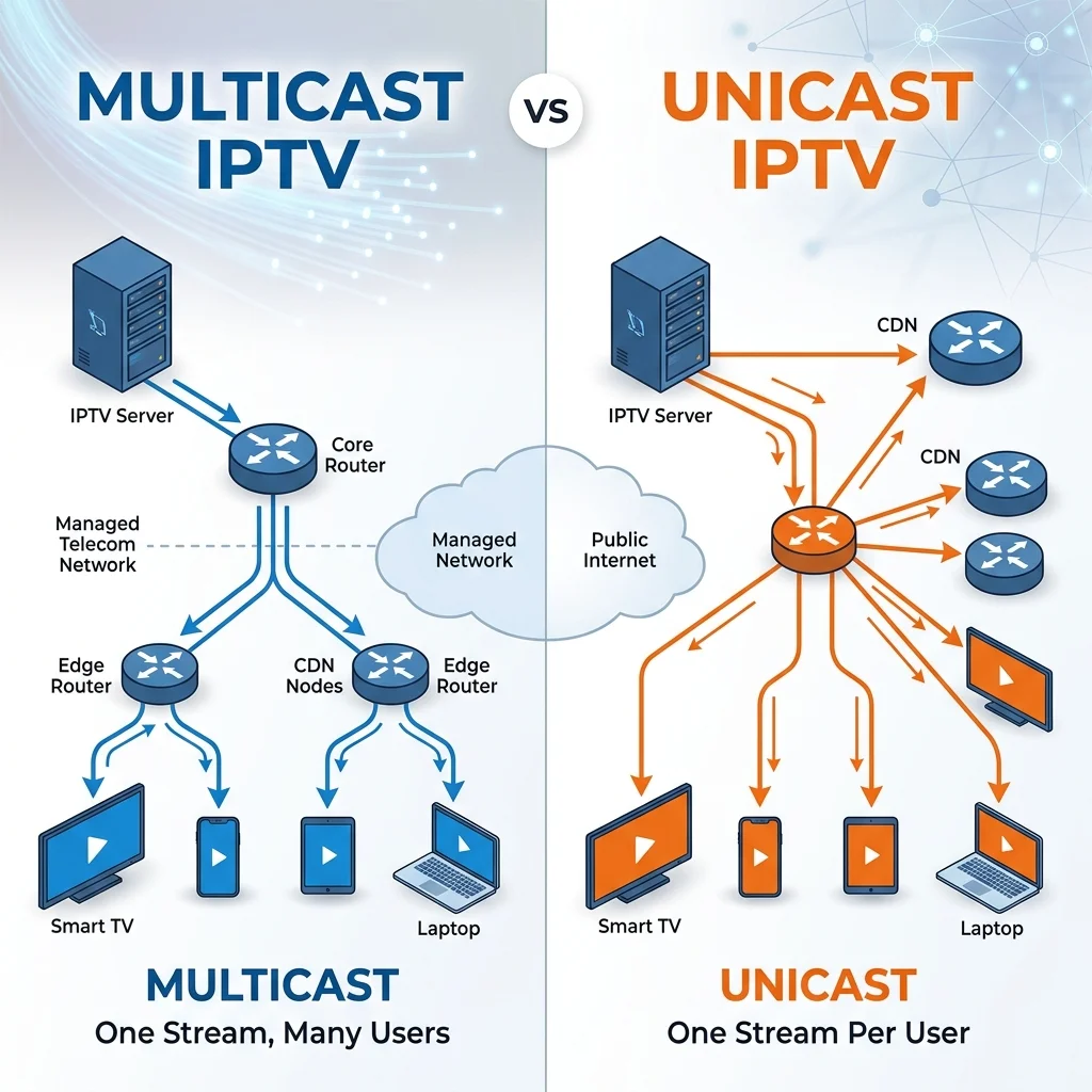
The fundamental difference between unicast and multicast delivery in IPTV lies in how data packets are replicated across a network: unicast establishes a distinct one-to-one connection for every single viewer, whereas multicast broadcasts a single stream that the network infrastructure dynamically replicates only when paths diverge to reach multiple subscribed devices.
Unicast Architecture: Linear Scaling and Individualized Delivery
In a unicast distribution model, each viewer receives a dedicated content stream originating from a central server or Content Delivery Network (CDN) node. When a client device (such as a smart TV, Firestick, or set-top box) requests a channel or video-on-demand (VOD) file, it establishes a unique, point-to-point connection with the streaming source. If ten thousand users are watching the same channel, ten thousand individual TCP or UDP connections are opened, and ten thousand identical copies of the video packets are transmitted across the network backbone.
This one-to-one relationship dictates a linear growth in bandwidth consumption at the source and core networks. The total bandwidth required (Btotal) scales directly with the number of concurrent users (N) and the bitrate of the individual stream (Bstream):
If an HD stream requires 8 Mbps, ten thousand concurrent viewers will consume 80 Gbps of egress capacity directly from the source or CDN. This direct correlation leads to high egress costs at scale for content providers. Despite these costs, OTT giants like Netflix and YouTube rely on unicast delivery because their platforms specialize in personalized viewing. Video-on-demand (VOD) services require individual state tracking for pausing, rewinding, or selecting custom audio tracks, making shared stream delivery impossible. To manage these constraints, OTT networks utilize distributed CDNs to cache content near local exchanges and employ Adaptive Bitrate (ABR) protocols to dynamically adjust quality.
Multicast Architecture: Constant Bandwidth and Group Replication
In contrast, multicast architecture is designed for one-to-many replication of simultaneous, identical streams, such as live sports or television broadcasts. The origin headend transmits a single stream addressed to a Class D multicast IP address within the 224.0.0.0/4 range (specifically 224.0.0.0 to 239.255.255.255). Because only a single copy of each packet is sent over the network core, the total backbone bandwidth consumed remains constant regardless of the audience size:
Instead of multiplying at the server, packet replication is handled at the edge routers and switches closest to the destination. This design is highly efficient, but it requires end-to-end network configuration control. Because public routers block multicast traffic for security and traffic control, multicast cannot traverse the open Internet. Instead, it is used by enterprise ISPs within private managed networks, often referred to as “walled gardens,” where operators control every routing hop to guarantee packet delivery.
The diagrams below illustrate the architectural differences and bottlenecks between these two models.

The diagram above illustrates the unicast bottleneck where the origin server must egress separate streams for every destination, saturating the core links.

The diagram above shows the multicast tree topology where a single stream copy is sent from the source and duplicated only at junctions where paths diverge.
These two approaches are represented in Canada by opposing service architectures. Bell Fibe TV uses a carrier-grade multicast platform (historically Microsoft Mediaroom/MediaKind) to deliver live TV over its private managed DSL and fiber networks. Replicating the stream at the local edge keeps bandwidth consumption low and protects television performance from household web traffic. Conversely, Rogers Xfinity TV delivers live broadcasts entirely via unicast ABR over cable and fiber. Each set-top box maintains a separate session, which places a high demand on Rogers’ local nodes and CDN capacity during high-concurrency events. For details on how these ISP network designs affect streaming performance, refer to the best internet for IPTV and IPTV services across Canada.
IGMP and IGMP Snooping: Managing Multicast Groups
Internet Group Management Protocol (IGMP) and IGMP snooping are network signaling protocols that coordinate multicast group membership and restrict the transmission of multicast media streams exclusively to the specific ports and devices that have requested them.
IGMP Join and Leave signaling
Internet Group Management Protocol (IGMP) operates at Layer 3 and is used by IPv4 hosts to report group memberships to local routers. The standard for carrier-grade IPTV is IGMPv3 (RFC 3376), which supports Source-Specific Multicast (SSM), allowing a set-top box to request a multicast stream from a specific source IP (S,G). This improves routing efficiency and security.
When a viewer changes channels, the set-top box sends an IGMPv3 Membership Report (Join) for the new channel’s multicast group. The router records the join and directs the stream down that network path. To maintain state, the router acts as an IGMP Querier, sending periodic General Queries (typically every 125 seconds) to which active hosts must respond. When switching away, the set-top box sends an IGMP Leave Group message. Modern IPTV networks use “Immediate Leave” (or Fast Leave) to instantly stop the stream and reclaim last-mile bandwidth, enabling fast channel changes.
IGMP Snooping
While IGMP operates at Layer 3, Layer 2 ethernet switches cannot inspect IP headers and default to flooding multicast traffic to all ports as if it were a broadcast frame. IGMP Snooping is a managed switch feature that prevents this flooding by intercepting IGMP Join and Leave messages at the switch fabric.
The switch maps the Layer 3 multicast IP address to its Layer 2 multicast MAC address, which always uses the IEEE prefix 01:00:5E. For example, the multicast group 239.192.10.5 maps to the MAC address 01:00:5e:40:0a:05. The switch records these associations in its Multicast Forwarding Table (MFT). When multicast frames arrive, the switch forwards them only to the physical ports with active group subscriptions. This isolates high-volume streams, preventing them from flooding other network segments and protecting Wi-Fi access points from traffic overload.
IGMP Proxying
In residential networks, set-top boxes often sit behind a local router that separates the home LAN from the ISP’s WAN. Because standard routers block multicast traffic and do not propagate IGMP messages across this boundary, IGMP Proxying is used.
An IGMP proxy runs on the local gateway, serving two functions. Downstream, it acts as a multicast router for the LAN, sending queries and listening for reports from set-top boxes. Upstream, it acts as a single IGMP host client to the ISP WAN. When a local box requests a channel, the proxy intercepts it, updates its database, and sends a single IGMP Join to the ISP router. The proxy then receives the incoming WAN stream and distributes it to the active local ports, traversing the NAT and firewall boundaries safely.
Why routers and switches need IGMP capability
In any multicast IPTV setup, ensuring that all network hardware supports and has enabled IGMP and IGMP Snooping is critical to prevent severe performance degradation.
Without these capabilities, the switch falls back to packet flooding, treating all multicast traffic as broadcast and forwarding high-bitrate video streams to every port. This results in immediate device drops and packet loss. Non-target devices, such as smart home hubs and computers, are forced to process and discard thousands of irrelevant packets, overloading their interfaces and CPUs.
Crucially, this flooding can cause wireless network collapse. Multicast frames are transmitted by Wi-Fi access points at low basic rates (such as 6 Mbps) to ensure connection stability for distant clients. Flooding a 15 Mbps stream over Wi-Fi will instantly saturate the wireless band, causing latency spikes, dropping smart devices, and crashing the home network.
To prevent these issues, network operators must configure an IGMP Querier and enable IGMP Snooping. If you experience buffering or network slowdowns, refer to our IPTV buffering guide to diagnose local bottlenecks. You can also review the sideloading process in Canada to optimize player settings, test your router with a Canada IPTV trial, and compare current IPTV pricing in Canada.
Streaming Protocols: HLS and MPEG-DASH in Action
Modern IPTV networks rely on HTTP-based streaming protocols like HTTP Live Streaming (HLS) and Dynamic Adaptive Streaming over HTTP (MPEG-DASH) to segment video files and distribute them dynamically based on changing network bandwidth.
HTTP Live Streaming (HLS) design
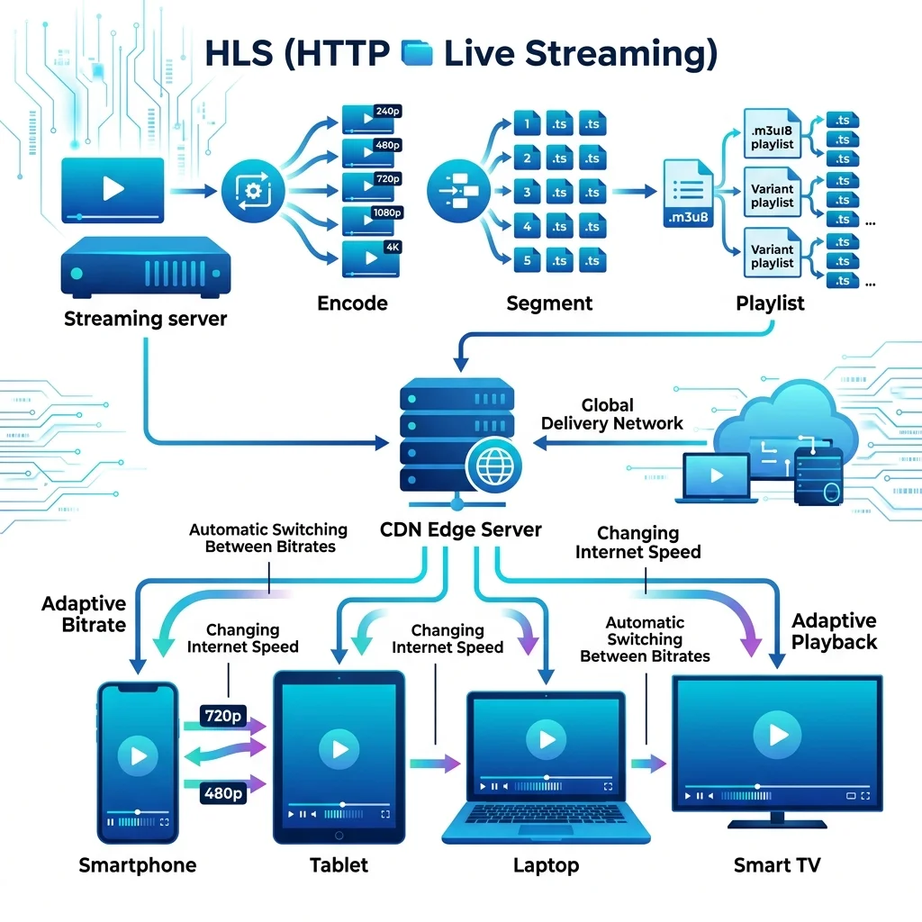
HTTP Live Streaming (HLS), defined in RFC 8216, is a stateless adaptive bitrate protocol that transmits video over standard HTTP by dividing streams into short segments, typically 2 to 10 seconds long. Originally, these segments used the MPEG-2 Transport Stream (MPEG-TS) container (.ts files). Modern HLS increasingly adopts fragmented MP4 (.fMP4) chunks aligned with the Common Media Application Format (CMAF) standard to minimize container overhead and latency.
The segment index is maintained in .m3u8 playlist files. The client first downloads a master playlist that acts as a directory referencing variant playlists, each corresponding to a different resolution and bitrate (e.g., 1080p at 6 Mbps, 720p at 3 Mbps).
The client then requests the media playlist for the chosen variant, listing segment URIs sequentially. The player fetches segments using HTTP GET requests. Under client-side adaptive bitrate (ABR) switching, the player measures the download speed of each chunk. If download time exceeds chunk playback duration, it requests a lower-bitrate variant; if bandwidth permits, it requests a higher-bitrate variant to prevent buffering. For playlist structure details, see the M3U playlist guide.
Why Apple created HLS
Apple introduced HLS in 2009 alongside the launch of the iPhone 3GS to replace Adobe Flash Player and the Real-Time Messaging Protocol (RTMP) on mobile devices. RTMP is a stateful protocol requiring persistent TCP connections (typically port 1935) between the server and player. This stateful architecture limited server scalability by requiring session memory for each client, and corporate firewalls frequently blocked its non-standard port.
Due to Flash’s high CPU overhead and battery drain, Apple banned it from iOS. HLS was designed to run over standard HTTP (port 80) and HTTPS (port 443) to bypass firewalls and NAT barriers. This allowed standard HTTP caches and global Content Delivery Networks (CDNs) to cache segments locally, shifting the scaling load from origin servers to edge nodes and enabling cost-effective global delivery.
MPEG-DASH and the MPD manifest
Dynamic Adaptive Streaming over HTTP (MPEG-DASH), standardized under ISO/IEC 23009-1, is an open, vendor-independent alternative to proprietary formats like HLS. Rather than using .m3u8 text files, DASH manages stream indexes via an XML-based Media Presentation Description (MPD) manifest.
The MPD manifest is structured hierarchically:
- Period: A temporal segment of the program, allowing providers to insert targeted ads or divide content into chapters.
- AdaptationSet: Groups interchangeable media streams, typically separating video, audio tracks, and subtitles.
- Representation: A specific encoding variant within an AdaptationSet, specifying a distinct resolution, bitrate, and codec.
- SegmentInfo / SegmentTemplate: Outlines how the client constructs segment URIs, referencing initialization metadata and duration timelines.
Cross-platform compatibility and differences from HLS
While both protocols deliver adaptive media over HTTP, they differ in governance, codec compatibility, and device support. HLS is Apple-proprietary, while MPEG-DASH is an open ISO/IEC standard.
Historically, HLS relied on the MPEG-2 TS container and H.264/AAC codecs. Though it now supports fMP4 and HEVC, legacy environments still use .ts segments. Conversely, MPEG-DASH is codec-agnostic, supporting advanced formats like VP9, AV1, and Opus natively within the same container framework.
Platform support is split. Apple platforms (iOS, macOS, tvOS) do not natively support MPEG-DASH, requiring JavaScript-based players (like Dash.js or Shaka Player) via Media Source Extensions (MSE). HLS, however, enjoys native support across Apple, Android, Smart TVs, and web browsers. To unify delivery, modern providers adopt CMAF, serving both HLS .m3u8 playlists and DASH .mpd manifests from a single set of cached media chunks.

| Protocol | Purpose | Used For |
|---|---|---|
| HLS | Adaptive HTTP streaming | Unicast Video-on-Demand (VOD), catch-up TV, and live streaming over the public internet to Apple and mobile devices. |
| MPEG-DASH | Adaptive HTTP streaming | Codec-agnostic adaptive streaming for Smart TVs, Android devices, gaming consoles, and web browsers. |
| RTSP | Stateful streaming session control | Remote control operations (play, pause, stop) in point-to-point connections, common in IP CCTV and legacy VOD. |
| RTP | Real-time media transport | Packetization, sequencing, and timestamp synchronization of live video/audio over UDP, typically used in multicast. |
| IGMP | Multicast group signaling | Managing group memberships on switches and routers, allowing devices to subscribe to live television multicast feeds. |
Transport and Control: RTSP, RTP, TCP, and UDP
IPTV networks coordinate session establishment, media synchronization, and physical packet routing by utilizing stateful control protocols like RTSP alongside high-efficiency transport layers such as RTP over UDP or HTTP over TCP.
RTSP — Stateful session control
The Real-Time Streaming Protocol (RTSP), defined in RFC 7826, is a stateful application-level protocol designed to control media servers. Acting as a “network remote control,” RTSP manages the playback state but does not transport the video payload itself. It keeps track of the connection state on the server by maintaining an active session identifier for each viewer.
The control session uses structured TCP commands:
- OPTIONS: Discovers supported methods.
- DESCRIBE: Retrieves stream metadata using Session Description Protocol (SDP).
- SETUP: Allocates port pairs for data (RTP) and statistics (RTCP).
- PLAY: Starts packet delivery.
- PAUSE: Halts streaming while preserving state.
- TEARDOWN: Terminates the session, freeing server resources.
RTSP remains common in IP CCTV systems due to low latency. However, consumer IPTV has abandoned it. Because RTSP is stateful, servers must maintain session context for every viewer, limiting scalability. It also requires custom ports (typically TCP port 554), which struggle to traverse consumer NATs and firewalls.
RTP — Real-time transport
The Real-time Transport Protocol (RTP), defined in RFC 3550, is the standard packet format for transporting live audio and video. While RTSP manages session state, RTP packages the raw media payload and runs over UDP to prioritize speed.
The RTP header provides critical fields for stream reassembly:
- Sequence Number: A 16-bit counter used by the client to detect packet loss and reorder packets.
- Timestamp: A 32-bit field (typically using a 90 kHz clock for video) that reconstructs playback timing and eliminates jitter.
- SSRC (Synchronization Source): A 32-bit identifier mapping the packet to a specific stream source.
To maintain audio-video synchronization (lip-sync), RTP couples with the RTP Control Protocol (RTCP). Because audio and video use independent sampling clocks, their timestamps drift. RTCP solves this by sending periodic Sender Reports that map RTP timestamps to a common NTP wall-clock time. The client uses these mappings to calculate timing offsets and synchronize playback. For standard device configurations, refer to the IPTV setup guide.
TCP vs. UDP in video delivery
The transport protocol choice shapes IPTV performance. Providers must balance the absolute reliability of TCP against the low latency of UDP.
TCP is connection-oriented, guaranteeing in-order delivery. If a packet is lost, TCP halts delivery of subsequent data (head-of-line blocking) to retransmit the missing packet. This is ideal for static assets but problematic for live streaming, as retransmissions introduce latency and buffering.
UDP is connectionless and does not retransmit lost packets. A lost packet simply results in a temporary visual glitch, but playback continues uninterrupted. This characteristics makes UDP the choice for carrier-grade live multicast networks.
For public internet streaming (OTT), providers compromise by running HLS or DASH over TCP. By using a client buffer of 6 to 10 seconds, players can survive TCP retransmissions without stalling. For comparative performance analyses, see the best IPTV services across Canada or review IPTV pricing in Canada.
| Transport Protocol | Pros | Cons |
|---|---|---|
| TCP | • Guaranteed delivery ensures perfect image quality. • In-order delivery simplifies client decoder design. • Easily traverses standard web firewalls and NATs. |
• Head-of-line blocking causes playback freezes. • Higher header overhead and acknowledgment traffic. • Unsuitable for low-latency live multicast broadcasts. |
| UDP | • Minimal protocol overhead with no handshake delays. • No head-of-line blocking, maintaining steady stream flow. • Supports IP multicast for high-efficiency live delivery. • Ideal for ultra-low latency real-time video streaming. |
• No packet recovery; network congestion causes pixelation. • Packets can arrive out of order, requiring player reordering. • Frequently blocked by standard public internet firewalls. |
Adaptive Bitrate Streaming and Player Workflows
Adaptive bitrate streaming and client-side player workflows dynamically adjust video quality in real-time based on fluctuating network conditions to ensure uninterrupted playback while minimizing channel zapping latency.
How Adaptive Bitrate Streaming (ABR) works
Adaptive Bitrate Streaming (ABR) is a client-driven technology designed to deliver video over fluctuating networks. The IPTV headend compresses source feeds into an encoding ladder consisting of multiple quality representations, each targeting a specific resolution, frame rate, and bitrate. The video is then subdivided into discrete, self-contained segments, typically 2 to 6 seconds long.
The IPTV Encoding Ladder and Resolutions
To accommodate varying network speeds, encoders build a structured “encoding ladder” containing several profiles. The player dynamically selects the highest profile that the connection can stably download in real time:
- 240p (Ultra-Low / Mobile Edge)
- Typical Bitrate: 300 to 600 Kbps (H.264)
- Usage: Designed for extreme bandwidth constraints, such as mobile devices on weak 3G/4G connections or heavily congested subnets. While the image is highly compressed with visible compression artifacts, it keeps the audio playing and prevents stream stagnation.
- 480p (Standard Definition / SD)
- Typical Bitrate: 800 to 1,500 Kbps (H.264)
- Usage: Standard definition quality matching legacy analog broadcasts. Recommended for baseline connections or small mobile screens where detail density is less critical.
- 720p (High Definition / HD)
- Typical Bitrate: 2,500 to 4,000 Kbps (H.264 / H.265 / AV1)
- Usage: The entry point for high-definition streaming. Provides crisp images on laptops, tablets, and smaller desktop monitors without saturating average home bandwidth.
- 1080p (Full HD)
- Typical Bitrate: 5,000 to 8,000 Kbps (H.264 / H.265 / AV1)
- Usage: The industry baseline for modern TVs and home entertainment setups. Delivers sharp details and high-fidelity colors, requiring a stable broadband connection.
- 4K UHD (Ultra High Definition / 2160p)
- Typical Bitrate: 15,000 to 25,000 Kbps (H.265 / AV1)
- Usage: High-end display rendering for 4K Smart TVs and home theaters. It requires robust decoding hardware (SoC) and fiber-to-the-home (FTTH) connections to sustain high data throughput.
How Players Switch Between Resolutions Dynamically
The client player utilizes two core heuristic algorithms to determine when to switch resolutions:
-
Throughput-Based Heuristics (Rate Estimation): The player monitors the download duration (Tdl) of each media segment of size S. It calculates the instantaneous network speed as R=S/Tdl. Because internet routing is dynamic, the player applies an Exponential Moving Average (EMA) or Harmonic Mean to smooth out transient spikes: Rsmooth=α⋅Rcurrent+(1−α)⋅Rprevious If Rsmooth falls below the bitrate requirement of the current resolution profile, the player schedules a downshift to a lower resolution for the next segment.
-
Buffer-Based Heuristics (Buffer Occupancy): The player monitors the length of decoded video queued in RAM (measured in seconds of playback). The algorithm divides the buffer into zones:
- Danger Zone (< 4 seconds): If the buffer drains into this zone, the player immediately downshifts to the lowest possible resolution (e.g., 240p or 480p) to rapidly refill the buffer and prevent a full freeze (underflow).
- Buffer Filling Zone (4 to 10 seconds): The player requests segments matching the estimated throughput Rsmooth.
- Safe Zone (> 12 seconds): The buffer is highly stable, prompting the player to request the highest resolution profile that fits within Rsmooth.
-
Segment Boundaries and Seamless Transitions: The transition between resolutions occurs strictly at segment boundaries. Each chunk is encoded independently, starting with an IDR (Instantaneous Decoder Refresh) I-frame. Because IDR frames clear the decoder’s reference picture buffer, the player can seamlessly switch from a 480p chunk to a 1080p chunk. The decoder re-initializes its output dimensions without visual glitching, screen flashing, or audio interruptions.
The IPTV player rendering workflow
The rendering workflow inside an IPTV player is a highly orchestrated pipeline that translates network manifests into displayed frames:
- Download Manifest: The player fetches the index file (HLS
.m3u8or DASH.mpd) from the CDN. - Parse URLs and Representations: The parser extracts segment paths, audio tracks, and encoding details.
- Estimate Network Speed: A startup heuristic estimates connection speed using previous metrics or a HEAD request.
- Choose Initial Representation: The player selects a conservative initial bitrate to ensure rapid startup.
- Download Segment: An HTTP GET request fetches the first segment over TCP/TLS.
- Feed Decoder Buffer: The player demuxes the container (MPEG-TS or fMP4), pushing elementary audio and video streams into separate queue buffers.
- Hardware or Software Decode: The decoder pulls compressed frames from the queue. Software decoding uses the CPU, which can cause frame drops, whereas hardware decoding offloads this to dedicated ASIC chips on the SoC, as outlined in the IPTV setup guide.
- Display Frame on Screen: Decoded raw YUV frames are sent to the display controller, matching each frame’s Presentation Timestamp (PTS) against the master clock to maintain audio-video lip-sync.

Channel switching mechanics (CZT)
Channel Zapping Time (CZT) is the elapsed duration between when a user changes a channel and when the first frame of the new stream is rendered with synchronized audio. In IPTV, CZT is a function of network signaling, manifest processing, and decoder synchronization.
When a channel change is triggered, the player terminates the active stream, flushes the decoder buffers, and queries the provider’s middleware via API to get the new stream URL. The client then downloads the master manifest, chooses a starting representation, and retrieves the first media segment. The major bottleneck in CZT is filling the decoder buffer and aligning with the Group of Pictures (GOP) boundary. Decoders cannot start rendering from predictive P or B-frames; they must wait for an Independent Decoder Refresh (IDR) or I-frame, which contains a complete image. If the provider uses a 4-second GOP structure, the player may wait up to 4 seconds for an I-frame, adding significant delay. Modern players minimize CZT by pre-fetching manifests of adjacent channels, utilizing short GOP sizes (e.g., 1 second) on the server, or receiving a unicast burst of the most recent I-frame from a fast-channel-change server.
Networking Fundamentals: Routing, DNS, and Buffering
IPTV network performance depends on efficient multicast routing, fast DNS resolution, low-overhead security protocols, and strict control of latency, jitter, and packet loss.
Core networking stack for IPTV
IPTV delivery depends on whether the stream is multicast (inside closed operator networks) or unicast (across the public internet). Multicast routing in IPv4 is managed by the Internet Group Management Protocol (IGMPv3), enabling Source-Specific Multicast (SSM) where set-top boxes request streams from specific source IPs, reducing routing overhead and security risks. In IPv6, IGMP is replaced by Multicast Listener Discovery version 2 (MLDv2), integrated into ICMPv6, which uses link-local addresses for membership management.
For over-the-top (OTT) unicast services, client requests depend heavily on Domain Name System (DNS) resolution. Authoritative DNS servers supporting EDNS Client Subnet (ECS) pass the client’s IP subnet to direct requests to the nearest Content Delivery Network (CDN) edge node. High DNS lookup times add directly to zapping latency. For NAT traversal, unicast HTTP Live Streaming (HLS) runs over standard TCP port 443 (HTTPS), bypassing firewalls easily compared to legacy RTSP which requires STUN/TURN helpers. However, HTTPS introduces TLS encryption overhead. TLS 1.3 reduces the handshake to a single round-trip, but real-time symmetric decryption of the AES-GCM payload can saturate the CPU of low-powered streaming devices, causing rendering stutters.
Latency and jitter definitions
Maintaining broadcast-quality streaming requires strictly controlling four types of network delays:
- Propagation Delay: The time required for a signal to travel through fiber or copper. In fiber, light travels at ~200,000 km/s (5 μs/km). Streaming from a local CDN edge node keeps this delay below 5 ms, whereas routing across continents adds significant delay.
- Serialization Delay: The time to transmit a packet’s bits onto the physical medium, calculated as: Serialization Delay=Packet Size (bits)Transmission Rate (bps) For a 1,316-byte payload (10,528 bits) on a 10 Mbps WAN link, serialization takes 1.05 ms; on a 1 Gbps link, it drops to 10.5 μs.
- Queuing Delay: The time a packet spends waiting in router or switch buffers due to network congestion or bufferbloat.
- Jitter: The statistical variance in packet arrival times (Packet Delay Variation).
IPTV requires strict quality thresholds to avoid issues:
- One-way Latency: Must remain under 150 ms (ideally <50 ms for live sports).
- Jitter: Must be kept under 20 ms. Jitter above 30 ms exhausts the player’s network buffers, triggering drops.
- Packet Loss: Must be below 0.1%. Since IPTV media packets are not retransmitted, even 1% loss causes severe macroblock pixelation.
The physics of buffering
A buffer is a dedicated region of physical memory (RAM) that temporarily stores incoming stream data before decoding. Its size represents a direct tradeoff between latency and stability.
Under fluctuating network conditions, packet loss or jitter causes the write rate of the network downloader to fall below the read rate of the decoder. In TCP-based streaming, lost packets trigger retransmissions that halt the queue. In UDP streams, lost packets are simply dropped. Both result in Buffer Underflow—the state where the decoder buffer empties completely, forcing the player to freeze playback and display a loading spinner while it replenishes.
To prevent this, players employ a Jitter Buffer—an elastic queue that stores a small window of incoming packets and releases them to the decoder at a constant rate. While a larger buffer (e.g., 5 seconds) absorbs severe network jitter, it increases CZT and live latency. A smaller buffer (e.g., 200 ms) minimizes latency but risks frequent stalls. Furthermore, decoders cannot render a stream until they receive a complete I-frame keyframe. If a provider’s stream uses a large Group of Pictures (GOP) size to save bandwidth, the player must cache incoming predictive frames and wait up to several seconds for the next keyframe to arrive before rendering can begin. You can review how these performance factors differ across various platforms in the overview of IPTV services across Canada.
CDN Architecture: caching content at the edge
A Content Delivery Network (CDN) in IPTV architecture optimizes stream delivery by caching media segments geographically closer to end-users, reducing latency, core network congestion, and origin server load. Without decentralized caching, a centralized headend would crash under the concurrent load of thousands of simultaneous unicast streams. By distributing caching load across regional edge nodes, providers maintain stream quality, fast channel changes, and delivery stability.
The origin server
The origin server acts as the central repository and single source of truth for media assets. It ingests high-bitrate live video feeds from headend encoders and hosts the master libraries for Video-on-Demand (VOD) and Network Personal Video Recorder (nPVR) systems. Live video is transmitted to the origin using SRT or RTMP. Packaging software slices this video into sequential fragments (typically 2 to 6 seconds) and updates corresponding HLS .m3u8 or DASH .mpd playlists. Because the origin handles concurrent write and read operations, it utilizes high-throughput NVMe SSD storage arrays. To protect the origin from request storms when new segments are published, providers deploy an origin shield—an intermediate cache layer between the origin and regional CDNs that absorbs edge cache misses.
Edge caches
Edge caches are localized proxy servers positioned at the network’s periphery, collocated within regional central offices or Internet Service Provider (ISP) Points of Presence (POPs). They intercept client requests for video segments locally, preventing traffic from traversing the core backbone. When a set-top box (STB) requests a segment, the local edge cache serves it directly, delivering sub-5 millisecond response times. Edge caches run reverse proxy caching engines like NGINX or Varnish. Their caching behavior is governed by HTTP cache-control headers: live segments carry short Time-To-Live (TTL) values (under 2 seconds) and are cached in RAM, while static VOD assets carry long TTLs and reside on SATA SSDs. To optimize last-mile delivery, edge caches utilize TCP BBR congestion control, sustaining maximum throughput over wireless connections prone to transient packet drops.
Load balancing and Anycast routing
Distributing user requests across edge caches requires dynamic load balancing and Anycast routing. Under an Anycast scheme, multiple geographically separated edge caches are configured with the identical destination IP address. Using BGP, the ISP’s core routers advertise this Anycast IP, routing client packets along the path with the lowest BGP path cost. If a regional edge cache fails, BGP automatically updates routing tables to redirect client requests to the next closest active node without client-side interruption. For unicast sessions, providers combine Anycast with Global Server Load Balancing (GSLB) and HTTP redirections. The GSLB system analyzes the client’s subnet, performs health checks on regional nodes, and returns an HTTP 302 redirect to the least-loaded cache, balancing the network load.
Geo-routing and cache hit ratio optimization
To maximize CDN efficiency, providers optimize the Cache Hit Ratio (CHR), which measures the percentage of content requests served directly by the edge cache. A high CHR—ideally above 95% for VOD and 99% for live broadcasts—is achieved through precise geo-routing. Geo-routing systems parse the client’s IP subnet using the EDNS Client Subnet (ECS) extension to map them to the closest physical cache. To prevent “thundering herd” scenarios, edge nodes utilize request collapsing (coalescing). If hundreds of clients request an uncached live segment simultaneously, the edge cache collapses these into a single query to the origin shield, holding other client connections open until the segment is retrieved and distributed. Edge nodes also use Least Recently Used (LRU) eviction and pre-fetch subsequent segments predictively based on EPG schedules.

Real-World Architectures and Troubleshooting Guide
Deploying and managing IPTV networks requires a combination of controlled carrier-grade routing protocols and precise client-side diagnostics to resolve stream delivery degradations. While managed networks offer guaranteed packet delivery through dedicated virtual lanes, over-the-top (OTT) streaming platforms must rely on software-side heuristics to navigate unmanaged public routing hops.
Canadian real-world deployments
In the Canadian telecommunications market, service providers deploy distinct architectural models to deliver television programming:
- Bell Fibe TV: Bell delivers Fibe TV using the Ericsson Mediaroom (now MediaKind) IPTV middleware platform as a managed IP multicast system. On Bell’s Fiber-to-the-Home (FTTH) network, video traffic is logically separated from standard internet data at the datalink layer. The ONT splits the physical fiber line into virtual lanes using 802.1Q VLAN tags, assigning video traffic to VLAN 36 and public internet traffic to VLAN 35. The Bell Home Hub gateway handles IGMP proxying, while regional Alcatel-Lucent/Nokia routers prioritize VLAN 36 packets using DSCP 46 (Expedited Forwarding), preventing household web traffic from interfering with live streams.
- Rogers Xfinity TV: Powered by Comcast’s syndicated X1 / Ignite platform, Rogers Xfinity TV (formerly Rogers Ignite TV) uses a unicast Adaptive Bitrate (ABR) model. Streams are encapsulated in fragmented MP4 (fMP4) containers and delivered over Rogers’ Hybrid Fiber-Coaxial (HFC) DOCSIS 3.1/4.0 networks or FTTH drops. Rogers utilizes QAM-to-IP edge gateways and places local CDN cache nodes deep within its regional hub sites, prioritizing downstream video packets via DOCSIS service flows.
- Telus Optik TV: Operating in Western Canada, Telus Optik TV mirrors Bell’s architecture, leveraging MediaKind Mediaroom over Telus PureFibre. Live feeds are distributed via IP multicast using IGMPv3 Source-Specific Multicast (SSM), routing streams directly to client set-top boxes to guarantee sub-2-second latency.
- RiverTV: Canada’s first virtual Multichannel Video Programming Distribution (vMVPD) service is a pure Over-the-Top (OTT) platform running over the public internet. RiverTV lacks last-mile QoS control and relies on public CDNs (like Akamai) and client-side ABR players to dynamically scale resolutions to prevent buffering during local peak traffic hours.
Troubleshooting guide
When streams degrade, engineers and technicians analyze the physical, transport, and application layers to locate the point of failure:
- Freezing and Buffering: Underflow of the client’s jitter buffer. In unicast, this is caused by round-trip latency spikes or packet loss forcing TCP retransmissions. In multicast, it indicates a loss of IGMP state, causing routers to stop forwarding the UDP stream. Swapping Wi-Fi for Ethernet or using a VPN to bypass ISP Deep Packet Inspection (DPI) throttling resolves this.
- Pixelation and Artifacts (Macroblocking): Occurs when the decoder renders frames despite missing packets. In UDP multicast, dropped packets lead to corrupted P/B-frames, causing pixelation until the next I-frame keyframe arrives. Enabling IGMP Snooping on local switches prevents multicast traffic from flooding ports and causing congestion-induced packet loss.
- Audio Sync Drift: Caused by synchronization drift between Presentation Time Stamps (PTS) in the MPEG-TS container, or client hardware lag when decoding high-profile H.265 HEVC streams. Enabling hardware-accelerated decoding in player settings or re-initializing the audio/video decoders resolves this.
- Slow Channel Switching (High CZT): Caused by IGMP join/leave delays, slow DRM handshakes, or a long GOP (Group of Pictures) interval. If the encoder sets a 5-second GOP, the player must wait up to 5 seconds for the next keyframe. Enabling IGMP Fast Leave on the router and optimizing buffer settings reduces switching delay.
| Symptom | Technical Cause | Fix/Workaround |
|---|---|---|
| Stream Freezing & Buffering | Jitter buffer underflow due to packet drops or ISP DPI throttling. | Connect via Ethernet; run a VPN to bypass carrier-level DPI throttling. |
| Macroblocking & Pixelation | UDP packet loss on multicast subnets; lack of retransmission. | Enable IGMP Snooping on local switches; replace damaged Ethernet cables. |
| Audio Sync Drift | Discrepancy between Audio/Video Presentation Time Stamps (PTS). | Enable hardware-accelerated decoding; clear the player app cache. |
| Slow Channel Switching | High CZT caused by long GOP intervals or IGMP join propagation delays. | Enable IGMP Fast Leave on the router; optimize player buffer settings. |
For detailed hardware setup instructions, consult our IPTV setup guide. If you are looking for the best performance in Canada, read our comprehensive review of the best IPTV services across Canada to see which providers offer local edge caches. For users deploying their services on streaming sticks, our guide on how to install IPTV on Firestick provides step-by-step instructions. Finally, you can compare IPTV packages and pricing to find a subscription that matches your budget, or learn more about the underlying network protocols in our deep-dive into IPTV technology.
Is IPTV Legal in Canada and the United States?
IPTV is completely legal when delivered by licensed providers regulated by the CRTC in Canada or the FCC in the United States — the technology itself is neutral, but the content licensing determines legality.
Legal IPTV services
Licensed carriers pay rights fees to every broadcaster and sports property they carry. Bell Fibe TV, Telus Optik TV, and Rogers Ignite TV hold CRTC broadcasting distribution undertaking (BDU) licences and pay per-subscriber fees to CBC, TSN, and RDS. South of the border, Sling TV and Comcast X1 operate under FCC frameworks and carry ESPN, NFL Network, and regional sports under negotiated carriage agreements. Every channel on these platforms exists because a licensing cheque was written for it.
The grey-market and illegal IPTV problem
Grey-market providers strip that licensing layer entirely. They redistribute NHL, NFL, and EPL broadcasts — and hundreds of premium pay-TV channels — without a single rights agreement in place. The content is identical to what Bell or Rogers delivers, but no broadcaster has been compensated.
The risk runs deeper than copyright exposure. A 2023 industry audit found that 92% of illegal IPTV streaming domains contain malicious scripts, adware, or active phishing traps embedded in the player software or playlist files. Users who install unauthorised APKs or M3U loaders from unlicensed providers hand those scripts network-level access to their devices. Legal liability and cybersecurity exposure compound simultaneously.
If you want to compare IPTV packages and pricing across legitimate Canadian carriers, that is the safer and smarter starting point.
Why does my IPTV keep buffering?
Buffering on a legal IPTV service almost always traces to one of four root causes:
- ISP bandwidth throttling via Deep Packet Inspection (DPI). Carriers like Rogers and Videotron apply DPI during peak evening hours to identify and shape high-bandwidth streaming traffic. A VPN encrypts the stream header, preventing DPI from classifying the flow and restoring full throughput.
- Wi-Fi packet loss. Wireless interference between your router and set-top box introduces burst packet loss that the jitter buffer cannot absorb. Connect the STB directly via Ethernet to eliminate this variable entirely.
- Provider server overload. Shared unicast CDN nodes become congested during peak demand windows — typically 7–10 pm local time. Switching to a lower-resolution stream temporarily resolves most freeze events caused by this.
- Firewall blocking IGMP. If your provider uses multicast delivery, a router with multicast passthrough disabled will silently drop IGMP packets. Check your router’s multicast settings and enable IGMP snooping passthrough.
Frequently Asked Questions About How IPTV Works
What internet speed do I need for IPTV?
Minimum requirements depend on the stream resolution you are targeting. Standard definition (SD) requires 2 Mbps. High definition (HD) needs 5–8 Mbps of stable throughput. True 4K UHD delivery demands 20–25 Mbps with consistent headroom — not just peak speed. Beyond raw bandwidth, latency quality matters: jitter should stay under 20 ms and packet loss must remain below 10⁻⁶ (one lost packet per million) to prevent visible frame drops or re-buffering events.
Do I need a VPN to use IPTV?
No — not for legal, licensed providers. Bell Fibe TV, Sling TV, and similar regulated services work without one. That said, a VPN is worth considering for two practical reasons: privacy protection and bypassing ISP DPI throttling. When your ISP shapes streaming traffic during peak hours, a VPN encrypts the packet headers that DPI inspects, restoring full allocated bandwidth. The overhead is minimal — typically 5–15 ms of added latency — which is imperceptible during video playback.
What is the difference between IPTV and OTT?
The network is the defining difference. IPTV runs over a private, managed IP network owned or leased by the provider. That closed network carries quality of service (QoS) guarantees — the provider can reserve bandwidth, enforce latency ceilings, and prioritise video packets end-to-end. Bell Fibe TV is the clearest Canadian example. OTT services like Netflix and YouTube deliver streams over the public internet, which offers no latency SLA and operates on best-effort packet delivery. When your neighbourhood is congested, OTT degrades first because no bandwidth is reserved for it.
Can I use IPTV on a Firestick?
Yes. The Amazon Firestick runs a version of Android TV that supports sideloading third-party apps. TiviMate, IPTV Smarters Pro, and GSE Smart IPTV all accept M3U playlist URLs directly and build a full channel guide from the loaded playlist. For a complete walkthrough, read how to set up IPTV on your Firestick — the guide covers app installation, M3U URL entry, and EPG configuration from start to finish.
What is an M3U playlist in IPTV?
M3U is a plain-text file format originally designed for audio playlist sequencing. In IPTV, it has been repurposed as the standard method for delivering channel lists. Your provider gives you a single M3U URL. Your player app — TiviMate, VLC, Kodi — fetches that file and parses it line by line. Each entry maps a channel name to a stream URL, which resolves at playback time to either a unicast CDN endpoint (for on-demand or low-scale live content) or a multicast group address (for high-scale broadcast streams on managed networks). The M3U file is also where EPG data source links are typically declared, allowing the app to pull an electronic programme guide alongside the channel list.
Technical Standards and Authoritative References
To verify the protocols and engineering specs described in this guide, consult the official standards publications:
- HLS Protocol Specification: IETF RFC 8216 – HTTP Live Streaming
- IGMP Protocol Specification: IETF RFC 3376 – Internet Group Management Protocol, Version 3
- RTP Transport Protocol: IETF RFC 3550 – Real-time Transport Protocol
- RTSP Control Protocol: IETF RFC 7826 – Real-Time Streaming Protocol (RTSP) Version 2.0
- MPEG-DASH Specification: ISO/IEC 23009-1 – Dynamic Adaptive Streaming over HTTP (DASH)
- MPEG Transport Stream Container: ISO/IEC 13818-1 – Generic Coding of Moving Pictures and Associated Audio Information: Systems
- AV1 Codec Specifications: Alliance for Open Media AV1 Bitstream & Decoding Process Specification
- IPTV QoS Architectures: ITU-T Recommendation Y.1910 – IPTV Functional Architecture